Likes:
  Thanks:
  HaHa:
HaHa: 
 Reply With Quote
Ive used both setups,a di transducer,that came from my 597hd/di unit and I used a rotated hdsi transducerOriginally Posted by genec

.Both setups work well.i didnot use a switch with either setup but a switch can be used

 Crappie.com 3K Star General

Could you take a hb di transducer and use a switch to flip it on di on a 998,would di be better,or take old si ducer and lean it where one side would be straight down and not use other side and use it for straight down di then use a switch to go back to right ducer,or would it be any different? Just a thought.
God Demonstrated his love for us.Romans 5:8
Crappie.com 2K Star General
Ive used both setups,a di transducer,that came from my 597hd/di unit and I used a rotated hdsi transducer
.Both setups work well.i didnot use a switch with either setup but a switch can be used
Crappie.com 2016 Man of the Year
* Member Sponsor
We did all those experiments here Gene...
http://www.crappie.com/crappie/showt...=Experimenting
Both the scenarios you list will work...and it is definitely better DI images...(you can see some of mine and kosmo's DI images in the above thread...)
The switch is for mere convenience...in being able to choose the DI xducer of the stock HDSI xducer....
Or the DI xducer can be plugged right into the SI unit like kosmo did....
The rotated HDSI xducer also works...with even better DI results than the DI xducer...
Rickie
www.podunkideas.com <--Click here
------------
https://www.crappie-gills-n-more.com/
https://cornfieldfishinggear.com/
------------------------>> Pro Staff Sonar Advisor
Crappie.com 3K Star General
So if i use another si ducer and tilt it,would i have to block pins where it plugs in at? Also what cable would i need to switch back to orignal ducer?
God Demonstrated his love for us.
Crappie.com 2016 Man of the Year
* Member Sponsor
If using a HDSI xducer rotated 60°...it's best to eliminate the pinging to the opposite SI piezo that would be pointing up to the surface...(because the returns from this "upward pointing" piezo can cause some crazy reflections off the water surface...making the images yukky)...
There are 2 ways to disconnect the "upward pointing" piezo...
*Remove the pin in the HDSI cable end that feeds that piezo....
*Remove the pin in the AS SIDB Y cable that feeds to that same piezo....(I'll explain the need of the AS SIDB Y cable in a sec)...
This does not eliminate the electrical signal sent by the transmitter for that piezo ....it merely disconnects the channel to keep the electrical signal from reaching the piezo pointing "upward"...
The effect of this is that there will be no SI image on the side of the channel disconnected...it will just be black on that side of the SI image...
Because the HB "DI from SI" is a blend of the left and right SI data...this "black" side of the SI image is just not seen in the DI view....so the DI view will look normal...(with 1 exception)...
That exception is ...if the "DI Width" setting under the Sonar tab is set to "Narrow"....there will be no DI image at all...
The "Narrow" selection of the "DI Width" setting tells the processor to display "only the return echoes common in both the left SI and right SI"...
Because of the disconnected SI channel in the "Rotated SI xducer"....there are no echoes from the disconnected piezo to be "common" ....therefore no DI image on the display...
So, in a nutshell...make sure the "DI Width" setting under the Sonar tab is set to "Medium" or "Wide"...and the DI image will look like a normal DI Image on the display....
The SI image will look like a SI image with a black side on the disconnected piezo side....altho somewhat darker at the edge of the image...because the SI piezo is now pointing "down" instead of "sideways"...
_________________
Now the 2nd part of this setup requires the use of a 2nd HB xducer capable of 200kHz connected to the "Dual Beam" side of the HB AS SIDB Y cable ....
This is because the 2d piezo in a "rotated" orientation xducer aims the 2d sound pulse to the side at an angle...instead of straight down....causing erroneous depth readings that confuse the processor...
This 2nd xducer capable of 200kHz can be any HB xducer with the "house shaped" connector end...because the AS SIDB Y cable is only going to connect the 2d channel ...
When connected to the "Dual Beam" leg of the AS SIDB Y cable ...(there's only 2 wires in the "Dual Beam" leg of the AS SIDB Y cable ....1 wire going to the 2d piezo - 1 wire to drain/ground )....
____________
Now if you want the convenience of switching back to a regular HDSI xducer for normal operation...you can add to the above mix ...a HB TS3 switch ....
The above AS SIDB Y cable configuration using the rotated xducer plugs into 1 leg of the HB TS3 switch ...
The regular oriented HDSI xducer plugs into the 2nd leg of the HB TS3 switch...
The HB TS3 switch position then dictates which xducer setup to use ....
Clear as mud...??
Rickie
Last edited by rnvinc; 06-27-2014 at 11:28 AM.
www.podunkideas.com <--Click here
------------
https://www.crappie-gills-n-more.com/
https://cornfieldfishinggear.com/
------------------------>> Pro Staff Sonar Advisor
Crappie.com 3K Star General
Crappie.com 2K Star General
Genec,what pictures would you like to see
Crappie.com 3K Star General
some of your di off a slanted ducer verses off of di ducer,would like to know if its worth messing with,thanks
God Demonstrated his love for us.
Crappie.com 2016 Man of the Year
* Member Sponsor
In case others have not seen my shots in the other thread...:
Here's some examples of the same brushpile..scanned from the same direction...1 right after the other...
DI from SI....
DI xducer...
HDSI rotated 60°
Rickie
Last edited by rnvinc; 06-27-2014 at 06:16 PM.
www.podunkideas.com <--Click here
------------
https://www.crappie-gills-n-more.com/
https://cornfieldfishinggear.com/
------------------------>> Pro Staff Sonar Advisor
Crappie.com 2K Star General
Genec,both the 597di transducer and the rotated hdsi transducer perform better than the di from si.the 800kHz is were theres a big difference. The first thing that stands out when use either method ,is when the unit is set to 800,bottom will show as a white line.you can tell theres nore signal strength being dirrected to that area were water column meets the bottom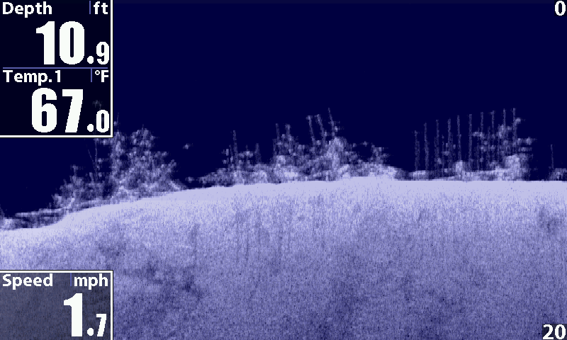
Posting Permissions