Thanks:
 Reply With Quote
V2 foot control wiring. These wires make up the cable from the V2 foot control.
Found this drawing on c.com in my photo stuff

 HaHa: 0
 Crappie.com 2011 Man of the Year
* Crappie.com Supporter
Crappie.com 2011 Man of the Year
* Crappie.com Supporter

I will draw up wiring how to's once I understand what i am dealing with.. All functions on the foot pedal work except steer, right??
Member BS Pro-Staff and Billbob Pro-Staff
Proud Member of Team Geezer... authorized by: billbob and "G"blueball LIKED above post
Crappie.com 2011 Man of the Year
* Crappie.com Supporter
V2 foot control wiring. These wires make up the cable from the V2 foot control.
Found this drawing on c.com in my photo stuff
Member BS Pro-Staff and Billbob Pro-Staff
Proud Member of Team Geezer... authorized by: billbob and "G"
Minnow
That is correct all functions work except for steering. I will hop back out into the garage after work today and see what I can come up with.
Crappie.com 2011 Man of the Year
* Crappie.com Supporter
The key to the puzzle is the yellow and green wires.
Sent from my SM-A526U1 using Crappie.com mobile app
Member BS Pro-Staff and Billbob Pro-Staff
Proud Member of Team Geezer... authorized by: billbob and "G"
Crappie.com 2011 Man of the Year
* Crappie.com Supporter
Also need the part number of the power control board. Is it 12v or 24v? Is it an add on Ipilot upgrade or is it from factory with ipilot?
I dug up a new relay module you can have if you decide to do this. I will set relay board up for simpler wiring.
Member BS Pro-Staff and Billbob Pro-Staff
Proud Member of Team Geezer... authorized by: billbob and "G"
Crappie.com 2011 Man of the Year
* Crappie.com Supporter
Waiting on answers.
Member BS Pro-Staff and Billbob Pro-Staff
Proud Member of Team Geezer... authorized by: billbob and "G"
Minnow
I am sorry for the delayed response on my part, I came down with something and I've been sick the past couple of days. My unit is is a 2020 24v powerdrive that was fitted from the factory with iPilot. I plan on making it out to the garage today sometime to dig a bit a deeper. Thanks again for your help.
Crappie.com 2011 Man of the Year
* Crappie.com Supporter
Not trying to rush you. Get well first. I don't mind helping folks, but over the years my skeptic level has risen concerning sincerity.Originally Posted by Sirak

Member BS Pro-Staff and Billbob Pro-Staff
Proud Member of Team Geezer... authorized by: billbob and "G"
Minnow
I snapped a couple of quick pics while I was out tinkering today. I will attach them here.
This is the control board that is in the base of the Powerdrive trolling motor. The 4 wires that are disconnected in the bottom right hand corner of the board all share contiunity with the corresponding color wire in the round connector that iPilot/Footpedal hooks into.
This is just a better angle to get your bearings.
This is the part # on the bottom of the control board in the iPilot head.
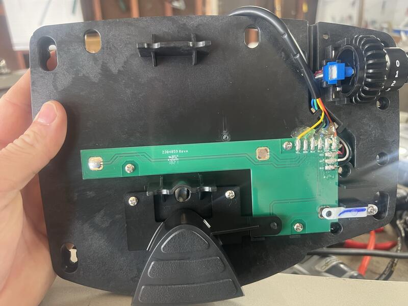
And finally this is the control board in the foot pedal everything matches the diagram you already provided.
Minnow
Posting Permissions